- +86 18120750932
- colin@xmsinuowei.com
- www.xmsinuowei.com

The definition of MLCC in electronics refers to multi-layer ceramic capacitors. As people know, a capacitor mostly includes two electrical conductors and one dielectric medium, and a ceramic capacitor uses a ceramic material as its dielectric medium. When stacking multiple ceramic capacitors (usually 500 layers or more) into a package, an MLCC is formed. Because of stacking so many layers together, MLCC has the advantages of small size and high capacitance.
1) MLCC Size
The size code of MLCC is a 4-digit number such as 0201, 0402, 0603, etc. The first 2 numbers refer to the length of MLCC and the last 2 numbers refer to the width of MLCC, for instance, 0201 means an MLCC with 0.02 inches long and 0.01 inch wide. In general, 0402, 0603, 0805 are the most commonly used sizes.
2) MLCC Dielectric
Dielectric directly determines the performance of MLCC. The multi-layer ceramic capacitor dielectric can be categorized into 2 classes regarding the definition of IEC/EN 60384-1 and 60384-8/9/21/22. Class 1 of MLCC has higher stability and accuracy; while Class 2 of MLCC has higher permittivity , but with lower stability and accuracy.
There are still other non-standardized classes for ceramic capacitors, but they cannot be manufactured with multi-layers, and there are more detailed explanations from Electronics Notes.
|
Class |
Description |
Suitable Applications |
Common Types |
|
Class 1 |
With high stability, accuracy and low loss |
Resonant circuits |
NP0(C0G) |
|
Class 2 |
With high permittivity (higher capacitance over a fixed volume) |
Smoothing, by-pass, coupling and decoupling applications |
X7R, X5R, Y5V |
Table 1. Class 1 and 2 of multi-layer ceramic capacitor dielectric (Source: Electronics Notes)
For Class 1 MLCC (like C0G, etc.), the first character refers to the temperature coefficient α, the second character refers to the multiplier, and the third character refers to the tolerance of the temperature coefficient. For example, C0G indicates an error of 0±30 ppm/°C, and U2J indicates an error of -750±120 ppm/°C.
|
1st Character |
2nd Character |
3rd Character |
|||
|
Letter |
α (ppm/oC) |
Digit |
Multiplier |
Letter |
Tolerance(ppm/oC) |
|
C |
0 |
0 |
-1 |
G |
±30 |
|
B |
0.3 |
1 |
-10 |
H |
±60 |
|
L |
0.8 |
2 |
-100 |
J |
±120 |
|
A |
0.9 |
3 |
-1000 |
K |
±250 |
|
M |
1 |
4 |
1 |
L |
±500 |
|
P |
1.5 |
6 |
10 |
M |
±1000 |
|
R |
2.2 |
7 |
100 |
N |
±2500 |
|
S |
3.3 |
8 |
1000 |
|
|
|
T |
4.7 |
|
|
|
|
|
V |
5.6 |
|
|
|
|
|
U |
7.5 |
|
|
|
|
Table 2. Code system for Class 1 regarding EIA-RS-198 (Source: Electronics Notes, Wikipedia)
For Class 2 MLCC (like X7R, X5R, Y5V, etc.), the first character refers to the lowest operating temperature, the second character refers to the highest operating temperature, and the third character refers to the capacitance change in the operating temperature range. For example, X7R indicates ±15% of capacitance change between -55°C and +125°C.
|
1st Character |
2nd Character |
3rd Character |
|||
|
Letter |
Lowest Temp. (°C) |
Digit |
Highest Temp. (°C) |
Letter |
Change of Capacitance |
|
X |
-55 |
2 |
+45 |
D |
±3.3% |
|
Y |
-30 |
4 |
+65 |
E |
±4.7% |
|
Z |
+10 |
5 |
+85 |
F |
±7.5% |
|
|
|
6 |
+105 |
P |
±10% |
|
|
|
7 |
+125 |
R |
±15% |
|
|
|
8 |
+150 |
S |
±22% |
|
|
|
9 |
+200 |
T |
+22% / -33% |
|
|
|
|
|
U |
+22% / -56% |
|
|
|
|
|
V |
+22% / -82% |
Table 3. Code system for Class 2 regarding EIA-RS-198 (Source: Electronics Notes, Wikipedia)
3) MLCC tolerance
As addressed above, the ceramic capacitor dielectric has already shown the tolerance of MLCC as well. In the range of -55 to +125°C., MLCCs of Class 1 have lower tolerances that are usually below 1%, while MLCCs of Class 2 have higher tolerances that are around 20%.
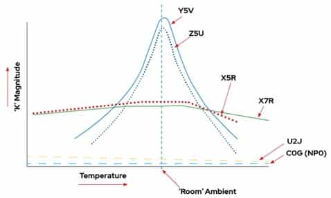
Fig. 1 Permittivity changes over temperature;
“K” refers to the relative permittivity of the dielectric material (Source: Kemet)
4) MLCC Capacitance
Based on different application needs, the capacitance of MLCC is with a large variety which ranges from 10pF to hundreds of μF (but 1nF~1μF in general).
5) Rated Voltage
The rated voltage can range from several volts to thousands of volts. The capacitance of an MLCC may change when applying the rated voltage, and it mostly occurs in X5R or X7R capacitors with ferroelectric materials.
Source:TECHDesign
Previous :
How to Properly Remove a Hose ClampNext :
Jubilee Clip


Copyright © Xiamen Sinuowei Automated Science and Technology Co., Ltd. All Rights Reserved.

Service online
 Language
 English
 français
 Deutsch
 русский
 italiano
 español
 português
 العربية
 日本語
日本語 한국의
한국의 ไทย
ไทย 中文
中文