- +86 18120750932
- colin@xmsinuowei.com
- www.xmsinuowei.com
Overview
Multilayer ceramic capacitors (MLCCs) are generally the capacitor of choice for applications where small-value capacitances are needed. They are used as bypass capacitors, in op-amp circuits, filters, and more.
Advantages of MLCC include:
Small parasitic inductance give better high-frequency performance compared to aluminum electrolytic capacitors.
Better stability over temperature, depending on the temperature coefficient.
Disadvantages
Small capacitance per volume, especially for class 1 dielectric materials (NO/COG).
DC bias instability.
Construction
MLCCs are made of alternating layers of metallic electrodes and dielectric ceramic, as shown in figure 1 below.
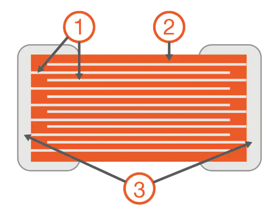
Figure 1: Construction of a multilayer ceramic chip capacitor (MLCC), 1 = Metallic electrodes, 2 = Dielectric ceramic, 3 = Connecting terminals
Image Source:http://en.wikipedia.org/wiki/Ceramic_capacitor#/media/File:MLCC-Principle.svg
Important datasheet parameters
Two very important datasheet parameters are temperature coefficient and voltage rating.
Temperature Coefficient
Class 1 ceramic materials (e.g., NPO, COG) have very low temperature coefficients, meaning that their capacitance varies very little over temperature. They also have low dielectric constants, meaning that capacitors built with class 1 materials have very small capacitance per volume. NPO and COG are very common class 1 temperature coefficients, and have a temperate coefficient of 0 and tolerance of +/-30 ppm.
Class 2 (X,Y,Z) ceramic materials are less stable over temperature, but have a higher dielectric constant, which means that capacitors with more capacitance are available in the same volume. X7R is a very common class 2 temperature coefficient, and X7R capacitors typically have tolerance of 5%, 10%, and 20%.
Table 1 helps decode temperature coefficients for class 2 MLCCs. Examples are included below.
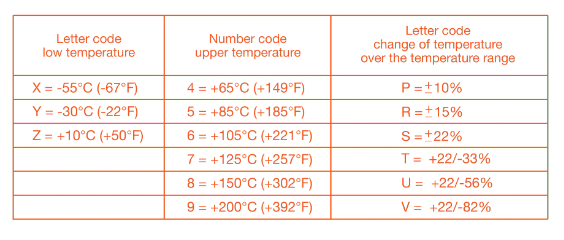
Table 1:Code system for IEC/EN 60384-9/22 for temperature ranges and capacitance changes over temperature
Image Source:http://en.wikipedia.org/wiki/Ceramic_capacitor#Class_2_ceramic_capacitors
Examples include:
X7R is rated to operate from -55 C to +125 C, with +/-15% change in capacitance over temperature range.
X5R is rated to operate from -55 C to +85 C, with +/-15% change in capacitance over temperature range.
Y5V is rated to operate from -30 C to +85 C, with +22/-82% change in capacitance over temperature range.
Capacitors with wider temperature ranges and more stable temperature characteristics tend to cost more.
Voltage Rating
The voltage rating indicates the maximum safe voltage that can applied across the capacitor. In practice, designers should use a capacitor with a voltage rating that is higher than the expected actual voltage, for reliability. Unlike aluminum electrolytic capacitors, MLCCs are non-polarized, so they can be put in a circuit in either direction with no explosion.
Frequency response
Figure 3 is a circuit model for a MLCC. MLCC have parasitic ESL (equivalent series inductance) and ESR (equivalent series resistance). These form a resonant circuit, where the minimum impedance is equal to the ESR, at the resonant frequency f=1/(2π√LC), where L is the ESL and C is the capacitance. Parasitics are related to packages sizes. SMT packages have lower ESL than through-hole packages.
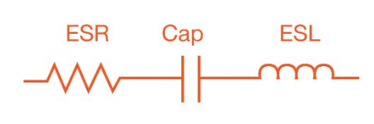
Figure 3:Circuit model of a real capacitor
The impedance of a capacitor decreases according to the formula Z=1/jωC, until the resonant frequency. At that point, the impedance of the capacitor is the ESR. As frequency increases, the impedance is dominated by the equivalent series resistance and looks inductive, causing the impedance to increase. Figure 4 is a plot of the impedance of a capacitor versus frequency that shows this behavior.
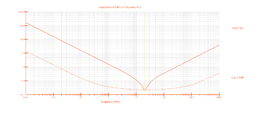
Figure 4:SpiCap plot of a MLCC impedance versus frequency
Image Source:Screen capture of AVX SpiCap 3.0 tool. SpiCap is available for download here: http://www.avx.com/spiapps/#spicap
Several capacitors with different values and packages can be used in parallel to provide a low impedance over a wide frequency.
DC bias drift
A DC bias across an X7R capacitor causes the capacitance to change slightly. Figure 5 is a plot of two 0.010 uF 0805 X7R capacitors. One capacitor has 50 V across it. We can see that the resonant frequency shifts by 10–20 MHz.
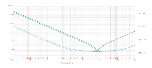
Figure 5:DC bias causes shift in capacitance
Practical considerations
Capacitors with stable temperature and tight tolerance should be used in feedback loops.
Bypass capacitors have less stringent requirements.
Choose a capacitor with a high voltage rating to provide margin.
Be aware of capacitance tolerance.
Be aware of temperature coefficient.
Be aware of ESL for high-frequency applications.
Be aware of ESR for high ripple current applications.
Parallel different values to provide wide frequency coverage.
Conclusion
This paper gives an overview of multilayer ceramic capacitors (MLCC), their construction, and important datasheet parameters with an emphasis on temperature coefficient, frequency response, and DC bias issues.
Source:RKER.IO


Copyright © Xiamen Sinuowei Automated Science and Technology Co., Ltd. All Rights Reserved.

Service online
 Language
 English
 français
 Deutsch
 русский
 italiano
 español
 português
 العربية
 日本語
日本語 한국의
한국의 ไทย
ไทย 中文
中文